Case study: a 3D-printed webcam mount, v1 to v3
An AI-assisted parametric design project, printed in-house: three versions, caliper measurements, and the reasoning behind every clearance. Version 3 is the latest and best.
The problem
A compact USB webcam such as the Logitech Brio 100 ships with a small folding clip meant to perch on top of a flat monitor. On a large curved screen, or on a shelf, that clip is a poor fit: the camera tips forward, shifts when the cable is touched, and cannot be aimed without nudging the whole thing. This project set out to build a dedicated mount that grips the camera's own clip, stays put, can slide along the top edge of a curved monitor, and lets the camera turn left and right.
It is also a good illustration of how Corsair Custom 3D approaches a custom part. The design was developed as an AI-assisted parametric project: the geometry was written as a script with named dimensions, with help from Claude, and built in Blender. Each version was printed in-house and checked against the real hardware. That loop of measure, model, print and test is what produces parts that fit.
Measuring first
Everything began with calipers rather than guesses. The camera's clip is a small hinged assembly: a flat top bar, a front tab and a rear flap that hangs down behind the monitor. The measured values drove the whole design:
- Top bar: about 37 mm wide and 6 mm thick, roughly 50 mm from hinge to hinge.
- Gap between the front tab and the rear flap: about 37.5 mm, the space a block must fit into.
- Rear flap: about 8.5 mm thick and 40 mm long, which defines the slot depth.
- Camera body: about 73 mm wide, 32 mm tall and 28 mm deep, used for clearance checks in the model.
- On the monitor: a 2 mm groove in the rear shell, measured at 24.5 mm below the top edge, which version 3 uses as an anchor.
In the script, these became named parameters. Changing one number, such as the clip gap, regenerates the entire model. That is the practical advantage of parametric design: when a print is off by half a millimetre, the fix is one edit, not a redraw. The same approach is available for customer parts, as described on the business parts page.
Fit clearances chosen on purpose
FDM plastic does not come out perfect, so clearances were set deliberately and carried through every version: 0.5 mm of play between the dock block and the clip gap, 0.5 mm of extra thickness in the flap slot, and 0.8 mm extra on the slot width. The dock block was modelled at 37.0 mm against a 37.5 mm gap, and the slot at 9.0 mm by 37.8 mm for an 8.5 mm by 37 mm flap. The result is a snug, removable fit that tolerates normal printing variation, echoing the tolerance advice on the printing services page.
The three versions
Use the steps below to compare versions, or scroll to read all three. The images are renders of the design files, not photographs. Version 3 is the one to look at first.
Version 1: a docking slot on a weighted round base
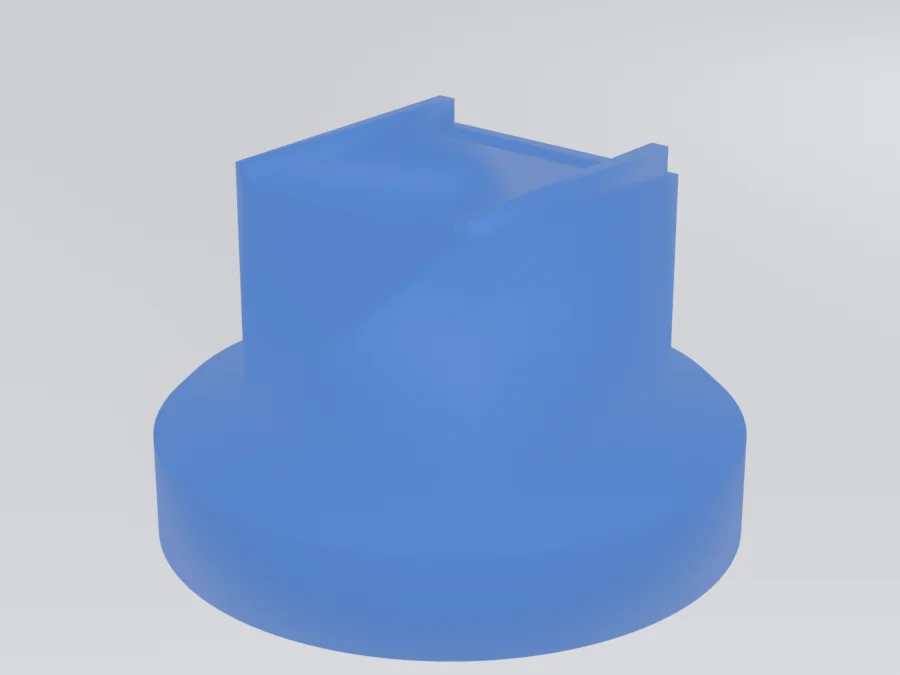
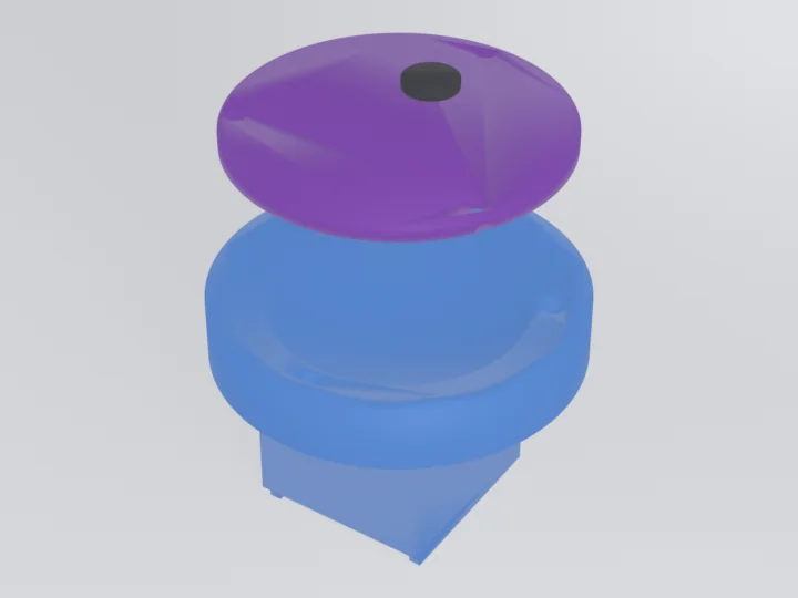
The first design was a round base, 90 mm across, with a rectangular dock rising from one side. The camera clip drops into a slot in the top of the dock, the front tab and rear flap straddle the block, and the camera hangs forward. A chamfered top edge avoids a sharp, easily chipped corner, and two small side guides keep the camera from twisting.
To stop a light base from sliding, the underside has a recessed pocket about 62 mm across and 11 mm deep for ballast such as steel shot, roughly 33 cm3, or on the order of 150 g when packed. A matching lid closes the cavity with three countersunk M4 screws into heat-set inserts, and four 12 mm TPU feet sit in shallow recesses to add grip. It worked for a shelf, but it takes up desk space and cannot follow a monitor's top edge.
Version 2: a clamp that rides on the monitor edge
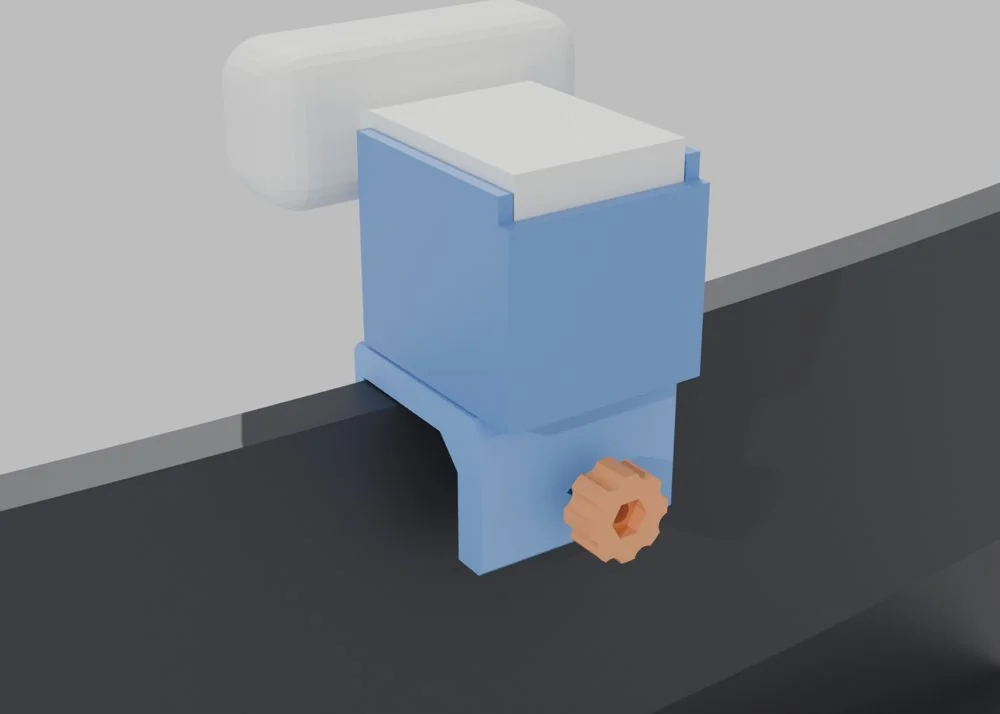
Version 2 moved the camera onto the monitor itself. The v1 dock, with its tested clearances, was kept unchanged and mounted on a C-shaped clamp that hooks over the top edge. The clamp's contact faces are bent to the screen's 1500R curve so they follow it, and the clamp is 44 mm wide. A slim front lip drops only 4 mm so it stays clear of the lit pixels, and recesses hold TPU or foam pads that protect the monitor finish.
A thumbscrew locked the clamp in place. Loosening it let the whole mount slide along the edge, and a pivot with a TPU friction ring and a stop pin allowed about 30 degrees of pan either way. The camera sits about 33 mm above the edge because the Brio's rear flap needs to sit fully in the dock slot. This version used a hardware-store M4 bolt, a captured nut, a glued knob and a TPU tip pad. It worked in principle but needed several separate parts for one adjustment.
Version 3: a printed M16 thumbscrew and a groove-seated point
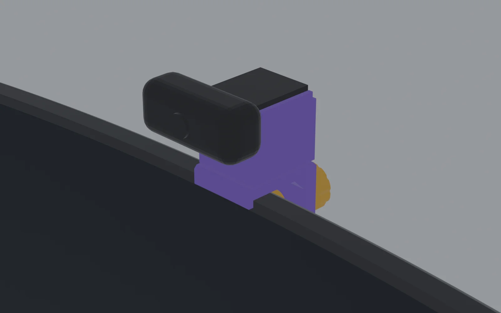
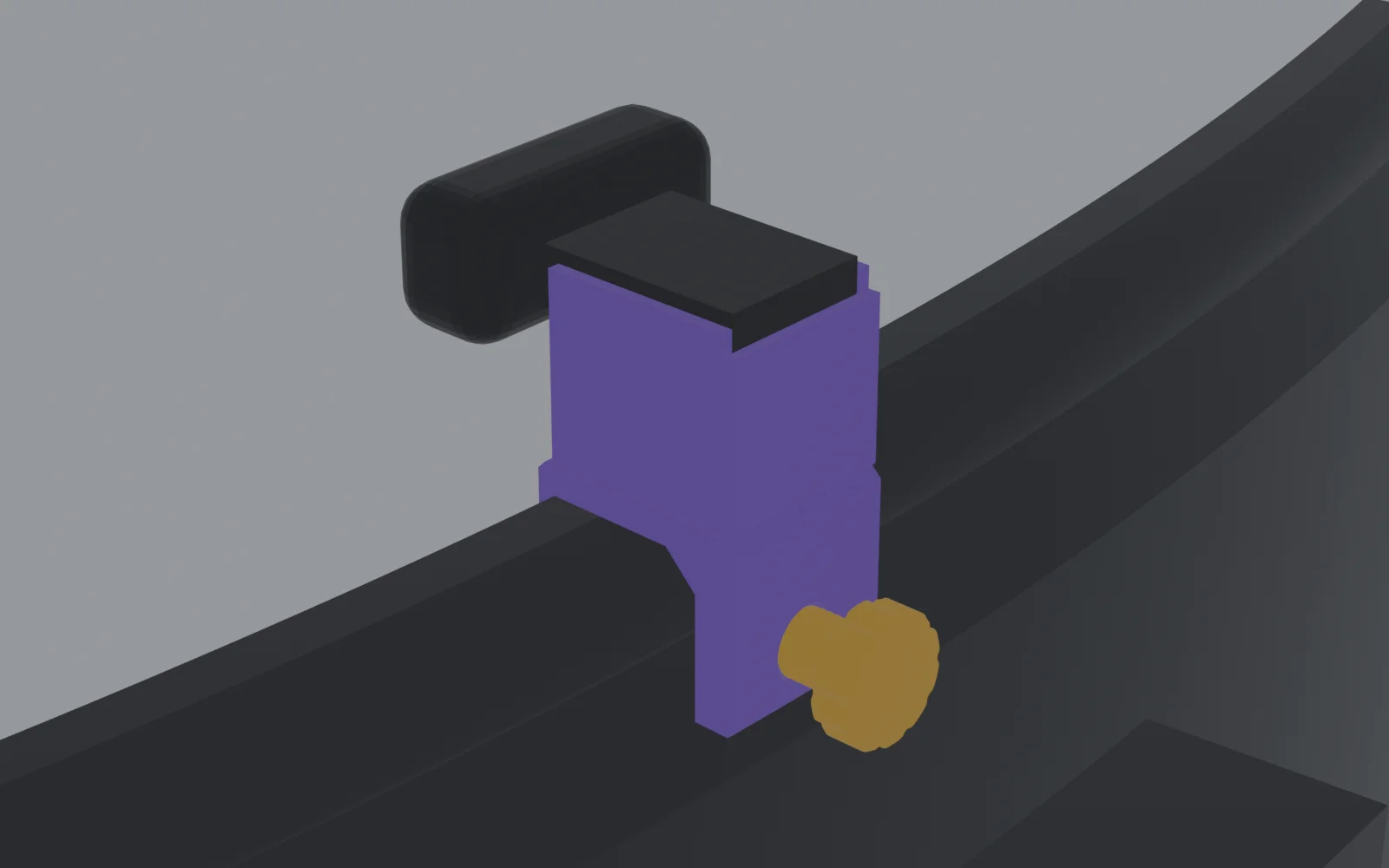
Version 3 is the latest and best. Its key change is the thumbscrew: a printed M16x2 coarse thread screw, 45 mm long, with an integral fluted knob 30 mm across and 10 mm thick. It threads directly into an M16 internal thread modelled into the clamp's rear jaw, so there is no nut, no insert and no glue. The bolt, nut, separate knob and TPU tip pad from version 2 all disappeared from the parts list.
The screw ends in a 2 mm point: a rounded 1.8 mm nose that widens to 5 mm over 2 mm, on a 5 mm neck. That point seats in the 2 mm groove on the monitor's rear shell, 24.5 mm below the top edge, which gives a positive stop rather than relying on friction alone. The rear jaw was made 10 mm thick, giving five turns of thread engagement, and its position moved so the screw lines up with the groove.
Pan range grew from about 30 degrees to 90 degrees each way, by lengthening the stop groove while keeping the same pin. In the model the camera clears the monitor and the clamp at every checked angle.
Thread fit
A printed thread is not an ISO thread, so the fit is designed around what FDM can hold. The screw's crest measures 15.8 mm and its root 13.4 mm. The matching jaw thread has a 14.1 mm minor diameter and a 16.4 mm major diameter. The teeth are thinned along the axis, leaving about 0.26 mm of normal gap per flank and 0.85 mm of radial engagement. The CAD interference check reads 0.00 mm3 between screw and jaw with the screw seated. If a particular printer makes the thread tight, the clearance can be adjusted by a few hundredths of a millimetre and the part regenerated.
Printing it
- Thumbscrew: printed knob down on the bed, point up. PETG is preferred and PLA is fine. Use 0.2 mm layers or finer and five or more walls. The thread's lower flanks sit at 60 degrees, which is normal for a vertically printed thread, so no supports are needed.
- Clamp: printed on its side so each layer contains the whole C-shaped profile. The bending stress then stays inside the layers instead of pulling them apart. The M16 hole is horizontal in this pose and its flanks are shaped to print without supports.
- Soft parts: the TPU friction ring and pads are printed flat in flexible filament.
Using it
Back the screw out, hook the clamp onto the monitor, then turn the screw in until the point drops into the groove. Snug it by hand only. The point concentrates load on the monitor's plastic, and a coarse M16 thread produces a lot of clamping force for very little hand torque, so there is no need to crank it. To reposition, loosen the screw about half a turn: the point stays in the groove and runs along it, so the mount slides sideways along the curved edge.
A hand calculation, not a full stress simulation, shows the clamp bridge seeing about 16 MPa at a hard 200 N of screw force, roughly a three-times margin on PLA. The design needs about 60 mm of free space behind the monitor's top edge and about 65 mm above it for the camera and knob.
Figures come from the design files and the fit report for each version and are rounded for readability. The monitor's rear shell was modelled from measurements plus a few assumed values, so the dimensions that matter should be re-measured on any new monitor before printing.
How AI assistance fit into the workflow
The assistant, Claude, helped write and refine the Blender Python scripts that build the parts, and helped sanity-check geometry such as slot clearance, a lowered rear wall that keeps clear of the clip's hinge, and the groove reach of the thumbscrew. Each script ends with a report that prints key numbers and runs interference checks between parts at several pan angles. Those printouts made each iteration quick to review.
The assistant did not replace measurement or test fitting. Calipers decided the numbers, and the printed parts were fitted to the real camera. Treating AI as a fast drafting partner and the physical object as the final judge is a good rule for any custom part. If you would like a design developed the same way for your own product or equipment, describe the problem on the contact page.
Lessons that transfer to other parts
- Measure the real thing. A design from catalogue dimensions alone would have been off by a fraction of a millimetre in several places.
- Name your dimensions. A parametric model makes the third revision cheap, not painful.
- Plan clearances. A fit that is exactly the same size as the mating part will not assemble. A few tenths of a millimetre gives a good snug fit.
- Use geometry instead of hardware. Version 3 replaced a bolt, nut, glued knob and pad with one printed screw.
- Orient for strength. Printing the clamp on its side keeps its bending load inside each layer.
- Iterate on purpose. Each version solved a specific problem observed in the one before.
What this means for your project
The same workflow applies to mounts, brackets, holders and enclosures for almost any object: send a photo, a description and a few measurements, and a first version can follow. Because FDM printing makes small changes cheap, you are not locked into the first attempt. Related reading: the R/C planes and jets page shows the same approach applied to aircraft parts, and the how it works page explains the ordering steps. The finished work from the shop is collected in the gallery.